| Note: This site and the data it contains have been reposted from an archive of Nolan Lee's original web site by Steve Johnson. |
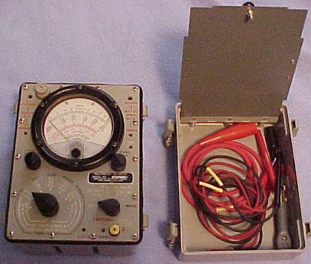
ME-297/U Multimeter
also known as AN/USM-223
Well, here's beta 2 dated 11/29/00. If you spot an error, holler back and I'll correct it.
I've had dozens of inquiries as to my success in tracking down the calibration instructions for the ME-297/U multimeter. Thanks to Paul Howard, I have them and have prepared a brief outline of "which trimmer pot does what" below:
This isn't rocket science, but if you don't understand the concept of ohms law for limiting the current flow thru the meter when calibrating and testing the current ranges or realize that the AC and DC voltages used for testing and calibrating the instrument can kill or maim you then you're best off just leaving it alone in the first place.
You've been warned, so don't come whining and bitching to me if you fry the meter or put an eye out or something.
You will need a copy of the operators manual TM 11-6625-654-14 for the parts layout and general information. If you don't have one, you can dowload one here: tm11-6625-654-14.zip as a zipped 1.2 meg archive containing an Adobe Acrobat version.
R50 is the adjustment for the current readings. It is set using the lowest current range of 0.25 dc ma at full scale while feeding precisely 0.25 ma dc thru the test leads. If yours pegs the needle, set the switch one range higher and then you can tell which direction to turn the trimmer and after you get close, return the range switch to 0.25 for maximum accuracy. This adjustment is critical as far as affecting the accuracy of the meter overall on all ranges, especially the non adjustable DC volts ranges.
There are no adjustments for calibrating the DC voltage ranges, but if R50 is correct, and none of the resistors in the voltage dividers are damaged, they should fall right into tolerances. Do not attempt to compensate and correct any errors in the DC voltage readings with the current adjustment above.
Next is R42. It is set using the 50 VAC range at full scale using 50 volts at 1000 Hz.
Then there is R41 which is set using the 2.5 VAC range at full scale using 2.5 volts 1000 HZ source. After adjusting this one, recheck the adjustment above for the 50V range. You may have to readjust it and run thru the pair of them a couple of times for the best compromise.
R36 is to set the resistance zeroing control. Set the meter to ohms X1 scale and center the Meter Zero control. Now adjust R36 to zero the needle. Do this with "good" batteries naturally.
That's it!